MAE 5190 - Fast Robots — Maia Hirsch
Hello! My name is Maia Hirsch, and I’m a PhD student in Robotics at Cornell University with a background in Mechanical Engineering. My main interests are robotics, actuation, sensing, and human–robot interaction. In my free time, I enjoy exploring creative projects that combine engineering and design. You can check out my insta @maiahirschlab to see all the cool things I make.
Lab 12: Inverted Pendulum
Objective
For this final lab, I decided to pursue the inverted pendulum challenge using closed-loop PID control. This problem requires fast, accurate angle estimation and a quick response from the motors.
Approach Overview
The inverted pendulum is an unstable system. Any small perturbation from the upright position will cause the car to fall unless the controller actively compensates by driving the wheels in the direction of the fall, like a Segway or hoverboard. My implementation uses a PD controller running on the Artemis, reading pitch angle from the ICM-20948 DMP, and driving the motors to maintain balance.
IMU Angle Detection
The first step was to figure out which IMU axis and what angle reading corresponded to the upright position. I added a debug print to Serial to output roll, pitch, and yaw while manually tilting the car.
I found the following:
- Flat on the ground: pitch ~ 0°
- Upright on rear wheels: pitch ~ -83°
- Tipping forward: pitch < -83° (more negative)
- Tipping backward: pitch > 83° (more positive)
This told me pitch was the correct axis, and that I needed to shift the reference so upright reads as 0°. I applied a fixed offset
float angle = global_pitch + 83.0;
With this correction:
- Upright = 0°
- Tipping forward = positive error
- Tipping backward = negative error
At some point, I think the IMU moved a little because when I held the car in the upright position, the angle read -1.4° rather than 0°. I decided to tune this setpoint parameter whenever necessary by sending a python command rather than hardcoding it.
ble.send_command(CMD.START_PENDULUM, "-3.5") # lean setpoint 3.5° forward
Controller Design
I implemented a PD controller. I omitted Ki on purpose as for an inverted pendulum the integral term accumulates error over time and can cause wind-up and instability making the tuning much harder.
float angle = global_pitch + 83.0;
float error = angle - pen_setpoint;

float P_term = pen_Kp * error;
float raw_D = pen_Kd * (error - pen_prev_error) / dt;
pen_d_filtered = PEN_D_LPF_ALPHA * raw_D + (1.0 - PEN_D_LPF_ALPHA) * pen_d_filtered;

float output = P_term + pen_d_filtered;
The D term is filtered with a low-pass filter (\alpha = 0.1) to reduce noise amplification from the derivative calculation. A safety cutoff stops the motors if the angle exceeds ±30° from vertical, since recovery is not possible beyond that point.
Motor direction mapping:
if (output > 0) {
    motorsBackward(constrain((int)abs(output), 85, 255));
} else if (output < 0) {
    motorsForward(constrain((int)abs(output), 85, 255));
}
BLE Commands
I added four new BLE commands. These allowed me to tune gains and retrieve data without reflashing the Artemis between attempts, which was essential for the long iterative process.
SET_PENDULUM_GAINS: received Kp and Kd from Python and stores them on the ArtemisSTART_PENDULUM: resets all PID state variables, accepts an optional setpoint offset to compensate for IMU mounting drift, and enables the controller flag so the main loop begins runningpidPendulum()STOP_PENDULUM: disables the controller flag and stops the motors.SEND_PENDULUM_DATA: transmits the logged arrays of timestamps, angles, errors, and motor outputs back to Python for plotting and analysis.
The DMP Speed Problem
Early attempts showed the car responding to tipping but never catching up with the fall. I first assumed that this was a gains problem and spent significant time tuning Kp and Kd across a wide range. Videos of these attempts are included below. No matter how aggressively I tuned, the car should just fall before the motors could respond in time.
The real issue turned out to be the DMP output rate. My initialize_DMP() had:
myICM.setDMPODRrate(DMP_ODR_Reg_Quat6, 2); // ~20Hz
For a fast-falling inverted pendulum, this is far too slow — the car can tip several degrees between updates. I changed the rate setting to 0, which runs the DMP at its maximum rate of ~57Hz:
myICM.setDMPODRrate(DMP_ODR_Reg_Quat6, 0); // ~57 - 58Hz
This change made an immediate dramatic difference. Now the car could stay upright for a few seconds.
To improve speed, I also added a continue statement in the main loop to skip all non-pendulum processing (ToF, drift, orientation PID) while the pendulum was balancing.
if (flag_pid_pendulum && dmp_ready) {
    if (get_yaw()) {
        pidPendulum();
    }
    continue;
}
Gain Tuning
All gains were hand-tuned iteratively using BLE commands from Python so I could change gains without reflashing:
ble.send_command(CMD.SET_PENDULUM_GAINS, "4.5|0.5")
ble.send_command(CMD.START_PENDULUM, "-1.4")
Although more gain combinations were tested, for the purpose of this writeup, here is a chart that outlines 3 combinations, each shown in a video below:
| Kp | Kd | result |
|---|---|---|
| 1.5 | 0.1 | Too slow — car falls backward consistently |
| 2.0 | 0.2 | Slow — car falls backward |
| 3.0 | 0.3 | Starting to pick up with the speed but could be improved |
| 4.5 | 0.05 | Oscillates too much because of the low Kd |
| 4.5 | 0.5 | Best — car stays upright up to 7 seconds |
| 6.0 | 0.5 | Fast, overshoots and corrections are hard to implement |
The general pattern I observed: too low Kp meant the motors were too slow to catch up. Too high Kp caused too many oscillations and the car overcorrected back and forth. Kd helped damp these oscillations, but if Kd was too high the car also did not have time to catch up.
Flowchart
Data Analysis
The following plot shows the pendulum sensor data and motor input for the best performing gains (Kp=4.5, Kd=0.5):
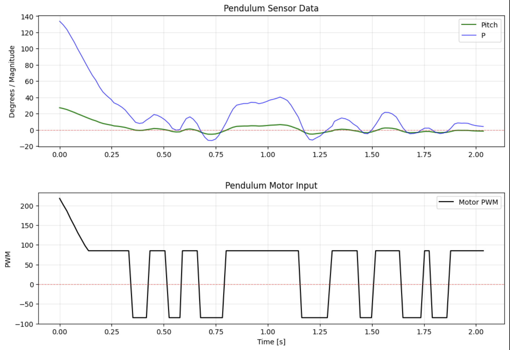
The top plot shows the pitch angle (green) and proportional term (blue) over time. Both start high — around 27° and 135 respectively because I was tilting the car from a horizontal position and placing it to be released from a perpendicular position with respect to the table (0°). Then we can see the plot converges toward the setpoint (0°) within approximately 0.5 seconds. After that, the angle oscillates within ±5° for the remainder of the run, showing the controller successfully maintaining balance.
The bottom plot shows the actual PWM sent to the motors. It starts at 220 — maximum effort to catch the initial release — then drops to ~90 as the car approaches vertical. It then settles into a square wave alternating between +85 and -85, which is the controller making continuous small corrections in opposite directions to fight gravity.
Results
Video 1 — Kp=1.5, Kd=0.1:
Video 2 — Kp=2.0, Kd=0.2:
Video 3 — Kp=3.0, Kd=0.3:
Video 4 — Kp=4.5, Kd=0.05:
Video 5 — Kp=4.5, Kd=0.5: Best result.
Video 6 — Kp=6.0, Kd=0.5:
Reaction video of the first time it worked 📍 Olin Library
Car maintains balance for up to 7 seconds before drifting off. I was very happy when it worked after days of debugging and trial and error.
Failed attempts when DMP was too slow
Here are some examples of the car’s slow reaction when DMP was set to 2 and not 0 as explained above.
Conclusion
The inverted pendulum challenge required solving two main problems: getting the angle measurement right, and making the control loop fast enough. Determining the offset gave the controller an accurate error signal. Increasing the DMP output rate from 20Hz to 57 Hz was the single most impactful change. The final PD controller with Kp = 4.5 and Kd = 0.5 achieves up to 7 seconds of sustained balance, which I’m quite happy about.
References
I referenced Stephan Wagner’s code and videos to have ideas and understand the expectations. I used Claude to create the flowchart.