MAE 5190 - Fast Robots — Maia Hirsch
Hello! My name is Maia Hirsch, and I’m a PhD student in Robotics at Cornell University with a background in Mechanical Engineering. My main interests are robotics, actuation, sensing, and human–robot interaction. In my free time, I enjoy exploring creative projects that combine engineering and design. You can check out my insta @maiahirschlab to see all the cool things I make.
Prelab
I implemented a BLE command system that allows me to start/stop PID control, update gains, and retrieve logged data wirelessly from Python.
I added the following new commands to my CommandTypes enum:
SET_PID_GAINS: sends Kp, Ki, Kd floats over BLEENABLE_MOTORS/DESABLE_MOTORS: toggle motor outputSTART_PID_POS_WITH_DATA: begins pID control and data logging with a target distanceSTOP_PID_POS_WITH_DATA: ends pID control and stops motorsSEND_PID_DATA: transmits timestamped ToF and motor output arrays back to Python
The Python workflow works like this:
ble.send_command(CMD.SET_PID_GAINS, "0.5|0.0|0.1")
ble.send_command(CMD.ENABLE_MOTORS, "")
ble.send_command(CMD.START_PID_POS_WITH_DATA, "304")  # 304mm = 1ft
# wait for maneuver
ble.send_command(CMD.STOP_PID_POS_WITH_DATA, "")
ble.send_command(CMD.SEND_PID_DATA,"")
PID runs non-blocking inside the main while (central.connected()) loop, checking checkForDataReady() on each iteration rather than blocking with a while(!ready) wait. Data is stored in timestamped arrays (pid_time_data, pid_tod_data, pid_motor_data) and sent over BLE after the maneuver completes.
For safety, I implemented a hard stop that triggered when BLE disconnects:
flag_pid_pos = false;
    flag_record_pid = false;
    motors_enabled = false;
    motorsStop();
    distanceSensor1.stopRanging();
    distanceSensor2.stopRanging();
This ensures the car stops if the Bluetooth connection drops mid-run.
Note on debugging BLE Disconnected: before starting this lab, and since lab 4, I kept having BLE disconnect issues whenver the motors started. I determined it was a hardware issue as Hayden Webb tested his working code on my car and kept running into this problem. I replaced the microcontroller and the BLE issue was resolved.
Lab Tasks
P/I/D Discussion
My task was to drive the car from a starting distance of ~1.2m and stop it exactly 204mm (1 foot) from the wall using closed-loop PID position with a VL53L1X ToF sensor.
Controller selection
I implemented a full PID controller. Starting with P-only control gave reasonable behavior as the car approached and settled near 304mm. However, the car had a small steady-state error that I wanted to eliminate. Adding the I term corrected this. The D term helped reduce overshoot during the fast approach.
Final gains: Kp = 0.05, Ki = 0.002, Kd = 0.005
A speed scale factor pid_speed_scale multiplies the PID output before clamping, allowing testing at 50%, 80%, and 100% of full speed without changing the gains.
Motor deadband: Motors stop when the error is within ±20mm of the target, preventing chatter near the setpoint. Forward motor PWM is floored at 0 (no floor needed since proportional output is already large far from the wall), and backward PWM is floored at 55 to overcome static friction.
Task 1: Frequency
The ToF sampling frequency is dependent on the timing budget. Because the goal here is to make a fast PID controller that can stop the car from running into walls, I opted for a 20ms timing budget, which is the fastest supported by our ToF sensors in long mode and yields a frequency of 50 Hz. To cofirm this, I printed times to the serial monitor as fast as possible while conditionally reading ToF data, like in lab 3:
if (flag_pid_pos) {
        static int pid_count = 0;
        static int tof_count_local = 0;

        // Update ToF reading only when new data is ready
        if (distanceSensor2.checkForDataReady()) {
          tof_count_local++;
          float new_dist = distanceSensor2.getDistance();
          distanceSensor2.clearInterrupt();
Testing revealed that the default timing bidget gave ~100ms intervals (10 Hz), which was far too slow for a responsive pID controller. After setting setTimingBudgetInMs(20), the intervals dropped to ~20 ms, a 50 Hz sampling rate and a 5x improvement.
Since the car needs to start beyond 1.3m to have room to reach full speed, short mode’s range limit was also a problem. I switched to long mode, which supports up to 4m. Together with the 20ms timing budget, the sensors trade some accuracy for speed and range, which is acceptable for this task.
Task 2: PID Results
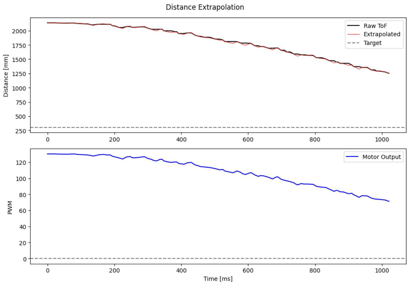
A PID controller combines proportional, integral, and derivative control terms to form the motor input u(t):
where e(t) is the error between the current ToF distance and the 304mm target.
A P controller is a good starting point, however it often experiences steady-state error. A PI controller can fix this by pushing the motors harder until the error is eliminated. A PID controller improves further by damping the motor input in response to quick rapid changes in sensor readings, like when the car closes in on the wall quickly. I built up the controller incrementally, starting from P and adding terms one by one.
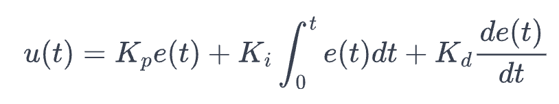
P Control
I started with the proportional term alone. The error is the difference between the current ToF reading and the 304mm setpoint. With Kp = 0.05, an error of ~1000mm produces an utput of 70, which is well within the 55-150PWM operating range, while an error of 50mm produces an output of 3.5, which falls below the motor threhold and causes the car to stop. This gives a natural deadband behavior near the target.
float computePID(float current_dist) {
    unsigned long now = millis();
    float dt = (now - pid_prev_time) / 1000.0;
    if (dt <= 0) dt = 0.001;
    pid_prev_time = now;

    float error = current_dist - pid_pos_target;
    pid_prev_error = error;

    return (pid_Kp * error);
}
The car approaches and settles near 304mm with one overshoot, but a small steady-state error persists.
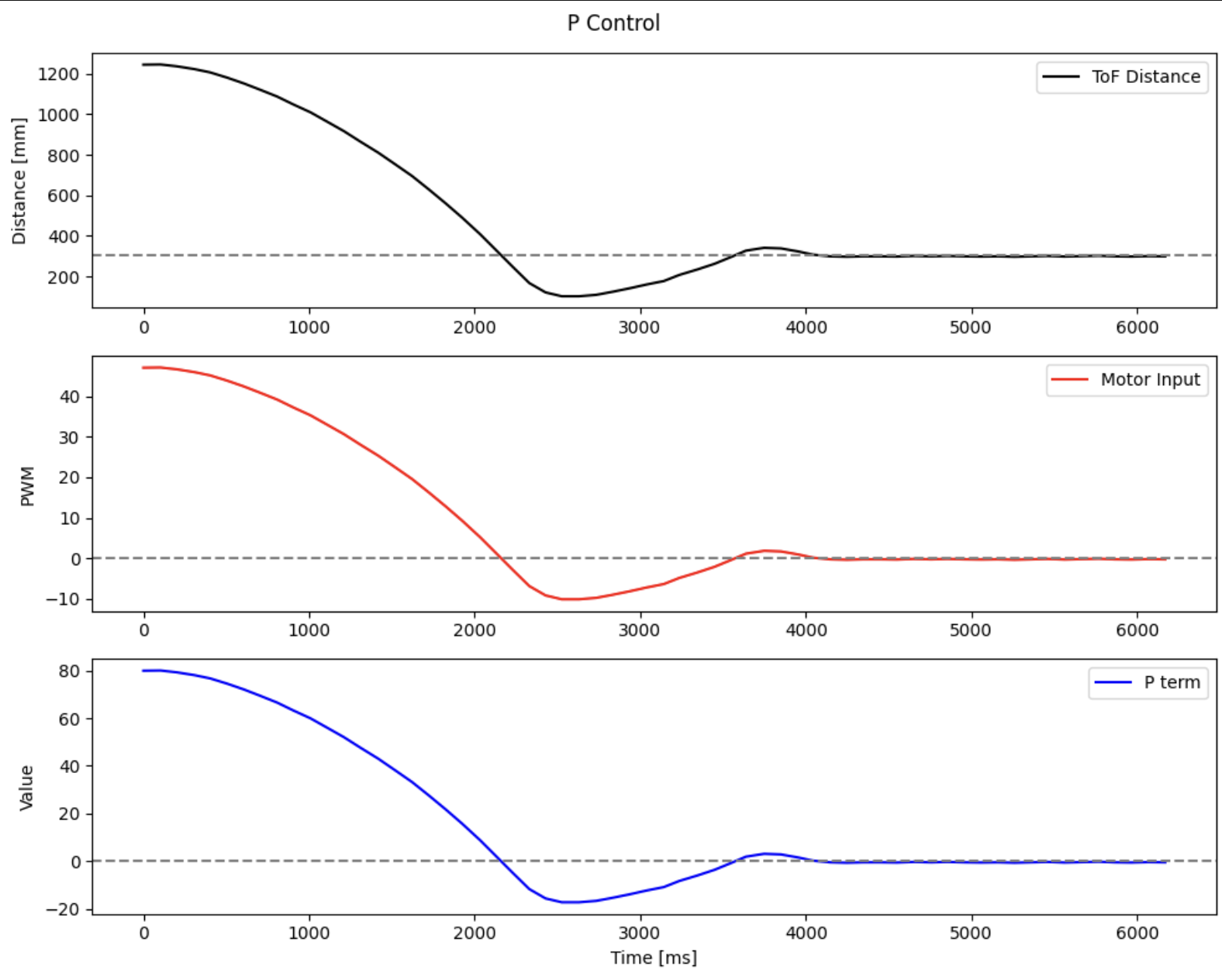
PI Control
To eliminate the steady-state error, I added the integral term. The integral accumulates error over time and provides a growing corrective push even when the proportional output has become very small. I kept track of dt between PID iterations to properly integrate
float error = current_dist - pid_pos_target;
pid_integral += error * dt;

float I_term = pid_Ki * pid_integral;

return (pid_Kp * error) + I_term;
After settling on Ki = 0.002, the car reliably reaches and holds 304mm. The I term is visible in the plot as a small but nonzero contribution near the setpoint that corrects the residual error left by the P term alone.
Task 3: PID Loop Rate
The VL53L1X ToF sensor was configured as follows:
distanceSensor2.setDistanceModeLong();
distanceSensor2.setTimingBudgetInMs(20);
distanceSensor2.setIntermeasurementPeriod(20);
The PID control loop, however, runs much faster than the sensor, as it is decoupled from the ToF read and runs every iteration of loop(). To measure the difference I added counters for both the PID iterations adn the ToF readings and printed them in the Serial Monitor:
if (flag_pid_pos) {
    static int pid_count = 0;
    static int tof_count_local = 0;

    if (distanceSensor2.checkForDataReady()) {
        tof_count_local++;
        float new_dist = distanceSensor2.getDistance();
        distanceSensor2.clearInterrupt();
        // update slope...
    }

    if (tof_curr_dist > 0) {
        pid_count++;
        if (pid_count % 50 == 0) {
            Serial.print("PID count: "); Serial.print(pid_count);
            Serial.print("  TOF count: "); Serial.println(tof_count_local);
        }
        // run PID...
    }
}
This gave a ToF sampling rate of ~50 Hz. The PID control loop, however, runs at ~800 Hz (about 16x faster than the sensor). To bridge this gap, I implemented distance extrapolation: between ToF readings, the controller estimates the current distance using the last measured velocity (slope):
float elapsed = (millis() - tof_curr_time) / 1000.0;
float extrap_dist = tof_curr_dist + tof_slope * elapsed;
where tof_slope is the velocity computed from the last two ToF readings:
float dt_tof = (tof_curr_time - tof_last_time) / 1000.0;
if (dt_tof > 0) tof_slope = (tof_curr_dist - tof_last_dist) / dt_tof;
The extrapolated distance is fed into computePID() every loop interation, while tof_slope is updated only when a new sensor reading arrives. This decouples the control rate from the sensor rate and allows the PID loop to respond faster than the sensor can provide data.
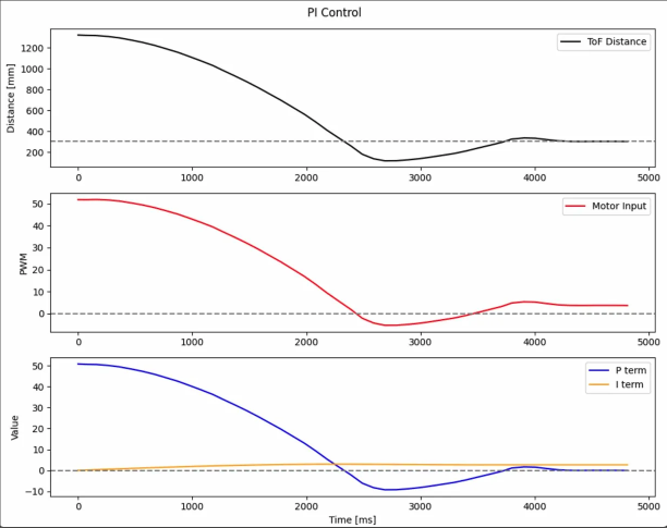
Task 4: Distance Extrapolation
To extrapolate distance between ToF readings, I stored the last two measurements as globals and computed the slope between them. The extrapolated distance is then the last known position plus the slope multiplied by the time elapsed since the most recent reading:
// Globals
float tof_last_dist = 0.0, tof_curr_dist = 0.0;
unsigned long tof_last_time = 0, tof_curr_time = 0;
float tof_slope = 0.0;

// Update slope when new ToF data arrives
if (distanceSensor2.checkForDataReady()) {
    tof_last_dist = tof_curr_dist;
    tof_last_time = tof_curr_time;
    tof_curr_dist = distanceSensor2.getDistance();
    distanceSensor2.clearInterrupt();
    tof_curr_time = millis();

    if (tof_last_time > 0) {
        float dt_tof = (tof_curr_time - tof_last_time) / 1000.0;
        if (dt_tof > 0) tof_slope = (tof_curr_dist - tof_last_dist) / dt_tof;
    }
}

// Extrapolate in PID loop
float elapsed = (millis() - tof_curr_time) / 1000.0;
float extrap_dist = tof_curr_dist + tof_slope * elapsed;
The effect of extrapolation is a relative smoothing of the step-like data generated by intermittent ToF readings. Instead of holding the last two known distance constant between readings, the controller tracks the estimated current position. The extrapolation can get its prediction wrong during sudden direction changes, causing small spikes int he extrapolated signal, but these are short-lived and don’t significantly affect controller performance.
Task 5: PID Control
PID Control
Adding the derivative term reduced overshoot. The D term senses how quickly the error is changing. When the car is closing in on the wall, the derivative goes negative and subtracts from the motor output, effectively breaking before the car overshoots. Since the derivative of a noisy sensor signal is very spiky, I applied a low-pass filter with alpha = 0.015
float error = current_dist - pid_pos_target;
pid_integral += error * dt;
pid_integral = constrain(pid_integral, -INTEGRAL_THRESHOLD, INTEGRAL_THRESHOLD);

float derivative = (error - pid_prev_error) / dt;
pid_d_filtered = D_LPF_ALPHA * derivative + (1 - D_LPF_ALPHA) * pid_d_filtered;
pid_prev_error = error;

return (pid_Kp * error) + (pid_Ki * pid_integral) + (pid_Kd * pid_d_filtered);
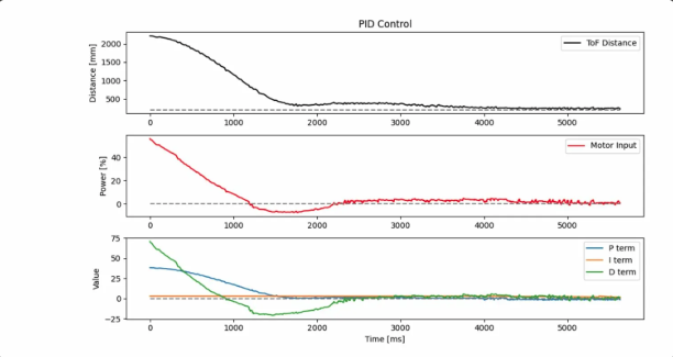
The Full 100% speed trial from ~1260mm shows the car approaching smoothly, overshooting to ~200mm, then backing up and settling at 304mm within ~3 seconds. The D term (green) goes negative during the fast approach, as expected. The I term (orange) remains small throughout, contributing only near the setpoint.
Derivative Kick
Derivative kick occurs when a sudden setpoint change causes a spike in the derivative term. In this implementation, kick is not a significant issue for two reasons:
- The setpoint is fixed at 304mm throughout the run (no jumps)
- The derivative is passed through a low-pass filter with alpha = 0.015, which heavily attenuates any high-frequency spikes before they affect motor output.
The plot below shows the raw (unfiltered) D term vs the filtered D term. The raw D term is noisy and spiky near the setpoint, but the filtered version remains smooth throughout.
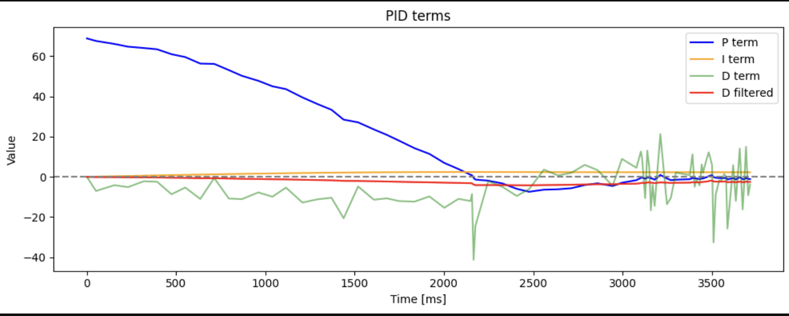
This shows that the LPF alone is sufficient to handle derivative kick without needing anything else.
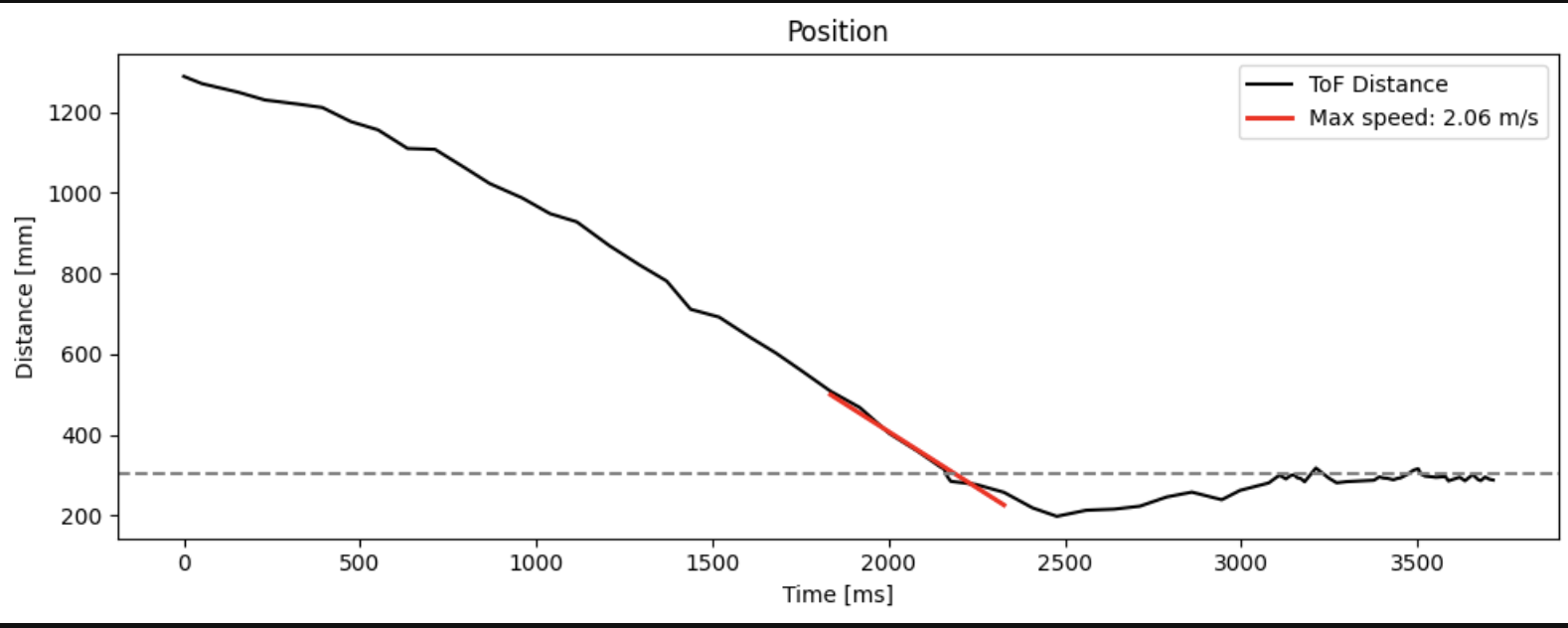
Task 6: Speed
At full speed (speed scale = 1.0), the car closes a ~1.26m distance in approximately 2.2 seconds. The maximum speed during the approach is 2.06 m/s, determined by fitting a line to the steepest portion of the distance vs. time curve.
(5000) Wind-Up Protection
Integrator wind-up occus when the error accumulates over a long approach, causing the integral term to grow far beyond what is needed to correct steady-state error. Once the car reaches the setpoint, the large accumulated integral takes a long time to unwind, causing overshoot and oscillation.
The plot below shows a simulation of what happens without wind-up protection, using Ki = 0.08 and no constrain on the integral. The I term (orange) grows to ~125 during the approach from ~926mm. Even after the car reaches the target and the P term drops to near zero, the I term remains large and would continue driving the motors aggressively.
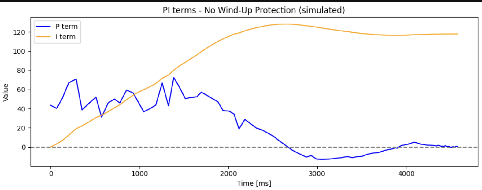
In practice, every time I attemped to run the controller without the integral constrain caused the Artemis to reboot mid-trial. My theory is that the unbounded integral drove motor commands large enough to crash the board before data could be transmitted. This is itself a strong argument for wind-up protection.
To prevent this, I added a constrain on pid_integral in computePID():
#define INTEGRAL_THRESHOLD 300

pid_integral += error * dt;
pid_integral = constrain(pid_integral, -INTEGRAL_THRESHOLD, INTEGRAL_THRESHOLD);
This caps the integral contribution so it cannot exceed ±300 in either direction. With protection and Ki = 0.002, the I term contributes only a small steady-state correction near the setpoint, and the controller runs stable.
Discussion
In this lab I learned how to build a PID controller from scratch and tuning it for a real physical system. I had studied PID in coursework before, but this was useful to close the gap between theory and pratice.
One of the first issues I had was that the motors simply weren’t running when PID started. The motors_enabled flag was never being set to true inside the START_PID_POS_WITH_DATA command handler, so the PID loop was computing outputs but the motor commands were silently ignored. Once that was fixed, a second issue surfaced: the controller was polling distanceSensor1 for data while distanceSensor2 was the one actually ranging, so the PID loop was starved of distance updates.
On the data collection side, the PID loop running at ~800 Hz filled the 2000-point buffer in under a second, which meant early plots showed the first 900ms of a trial and cut off before the car reached the target. Adding a pid_count % 8 downsampling condition extended coverage to ~6 seconds per trial.
As mentioned in the beginning, the notification handlers would sulently die between trials, when the car would start runing due to a disconnect of BLE but that was resolved by switching the microcontroller.
Despite these issues, the final controller settles reliably at 304mm from ~1.2m at full speed, with a max approach speed of 2.06 m/s.
References
I used Stephan Wagner’s writeup as a guide for task implementation and figure/videos needed. I let Hayden Webb borrow my car as his motors were not working properly. While working with my car, Hayden could not get past the BLE disconnect issue and so we were able to determine I had a hardware issue.