MAE 5190 - Fast Robots — Maia Hirsch
Hello! My name is Maia Hirsch, and I’m a PhD student in Robotics at Cornell University with a background in Mechanical Engineering. My main interests are robotics, actuation, sensing, and human–robot interaction. In my free time, I enjoy exploring creative projects that combine engineering and design. You can check out my insta @maiahirschlab to see all the cool things I make.
Lab 9: Mapping
Objective
The purpose of this lab is to map out the little world built in the lab using ToF distance readings collected from four marked positions of the world. The robot spins slowly in place at each position while recording distances, and the resulting readings are merged using transformation matrices to produce a line-based map for use in a simulation and future labs.
Control
Orientation control
I chose orientation PID control using the DMP chip for yaw estimation, the same controller I tuned in Lab 6. I collect 36 orientation data points in 10° increments, completing a full 360° rotation. At each step, the orientation PID runs until the yaw error falls within 4° and remains there for 500ms. Once settled, 5 ToF readings are collected from each sensor and averaged before moving to the next setpoint.
void run_mapping_scan(float start_yaw) {

  Serial.print("run_mapping_scan start_yaw=");
  Serial.println(start_yaw);
  map_data_index = 0;
  distanceSensor1.startRanging();
  distanceSensor2.startRanging();
  delay(200);

  for (int step = 0; step < MAPPING_STEPS; step++) {
    // 1. Compute target yaw
    float target = start_yaw + step * MAPPING_INCREMENT;
    while (target > 180.0) target -= 360.0;
    while (target < -180.0) target += 360.0;

    // 2. Run orientation PID until settled
    orient_setpoint = target;
    orient_integral = 0.0;
    orient_d_filtered = 0.0;
    orient_prev_time = millis();
    orient_prev_yaw = global_yaw;

    unsigned long step_start = millis();
    unsigned long settled_at = 0;
    bool settled = false;

    while (millis() - step_start < 3000) {
      if (get_yaw()) {
        float output = computeOrientPID(global_yaw);
        output = constrain(output, -200, 200);

        float err = global_yaw - orient_setpoint;
        while (err > 180.0) err -= 360.0;
        while (err < -180.0) err += 360.0;

        if (abs(err) < MAPPING_DEADBAND) {
          motorsStop();
          if (!settled) {
            settled = true;
            settled_at = millis();
          }
          if (millis() - settled_at > MAPPING_SETTLE_MS) break;
        } else {
          settled = false;
          motorsOrient((int)-output);
        }
      }
    }
    motorsStop();
    delay(50);

    // 3. Record actual yaw
    get_yaw();
    map_yaw_data[map_data_index] = global_yaw;

    // 4. Average MAPPING_READINGS from each sensor
    long sum1 = 0, sum2 = 0;
    int cnt1 = 0, cnt2 = 0;
    unsigned long tof_start = millis();

    while ((cnt1 < MAPPING_READINGS || cnt2 < MAPPING_READINGS)
           && millis() - tof_start < 1000) {
      if (cnt1 < MAPPING_READINGS && distanceSensor1.checkForDataReady()) {
        sum1 += distanceSensor1.getDistance();
        distanceSensor1.clearInterrupt();
        cnt1++;
      }
      if (cnt2 < MAPPING_READINGS && distanceSensor2.checkForDataReady()) {
        sum2 += distanceSensor2.getDistance();
        distanceSensor2.clearInterrupt();
        cnt2++;
      }
    }
Tuning the PID orientation controller
My orientation PID gains are:
- Kp = 3.5
- Ki = 0.001
- Kd = 0.3
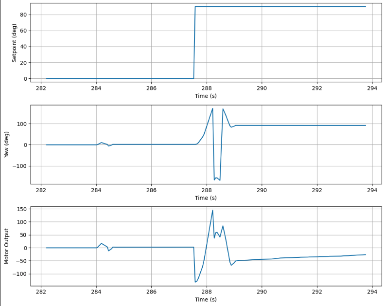
The controller is the same one I used in lab 6. The plot blow shows the yaw tracking a 90° setpoint cleanly, confirming the controller is well-tuned.
Error Analysis
From Serial Monitor, the yaw error per step was 1–3°. In the center of a 4×4m empty room, walls are 2m away in every direction. A 3° angle error at 2m will result in 2 × sin(3°) ≈ 105mm at the wall. On average with ~1.5° error this is closer to 52mm. The robot also exhibited slight translational drift (~50mm) during full scans due to errors on-axis spinning, combined this gives a maximum map error of ~150mm.
Read out Distances
I executed the mapping scan at each of the four marked positions: (-3,-2), (5,3), (0,3), and (5,-3).
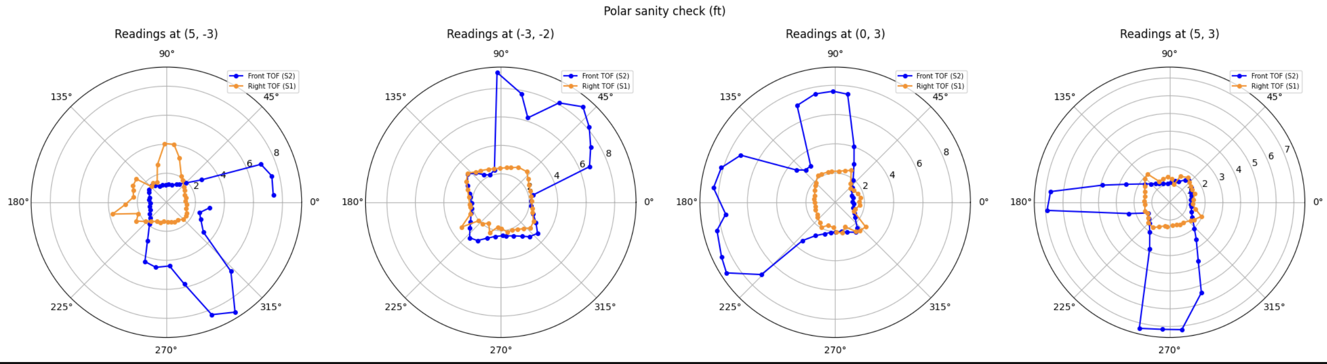
The polar plot shows reasonable shaped for each position, with distances that reflect what we expect from room geometry at each location. Here it is clear that sensor 1 is pointing at the floor.
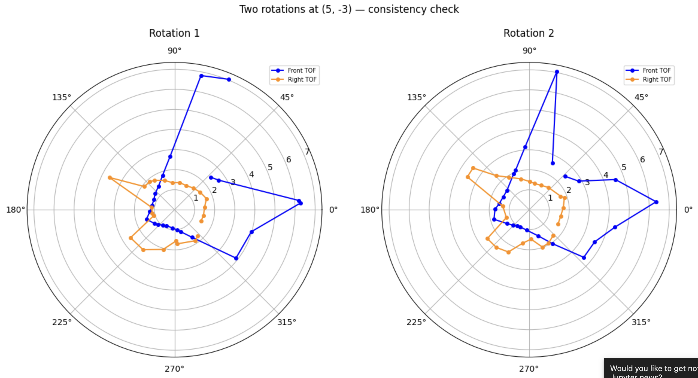
I performed two full rotations on my desk to assess scan repeatability. The front sensor (blue) shows good consistency between the two rotations — the large spike toward 45°–60° (pointing toward the open room interior) and the readings toward 0° and 315° (pointing toward the right and bottom walls) appear in both rotations at similar distances. The orange (right sensor) forms a consistent small ring close to the robot in both rotations, which as discussed above is due to the sensor pointing downward and hitting the floor rather than the walls.
Merge and Plot
Transformation Matrices
To convert each ToF reading from the robot’s local frame into the global room frame, I applied a 3×3 homogeneous transformation matrix at each angular step:
\[T(\theta, x_r, y_r) = \begin{bmatrix} \cos\theta & -\sin\theta & x_r \\ \sin\theta & \cos\theta & y_r \\ 0 & 0 & 1 \end{bmatrix}\]where $\theta$ is the robot’s DMP yaw at that step and $(x_r, y_r)$ is the robot’s known position in the room in mm.
Sensor 2 (front-facing) has its measurement along the robot’s $+x$ axis:
\[P_{room} = T \cdot \begin{bmatrix} d_2 + \text{dist} \\ 0 \\ 1 \end{bmatrix}\]Sensor 1 (right-facing) has its measurement along the robot’s $+y$ axis:
\[P_{room} = T \cdot \begin{bmatrix} 0 \\ d_1 + \text{dist} \\ 1 \end{bmatrix}\]where $d_2 = 90$ mm (sensor 2 forward offset) and $d_1 = 40$ mm (sensor 1 rightward offset).
A Note on Sensor 1
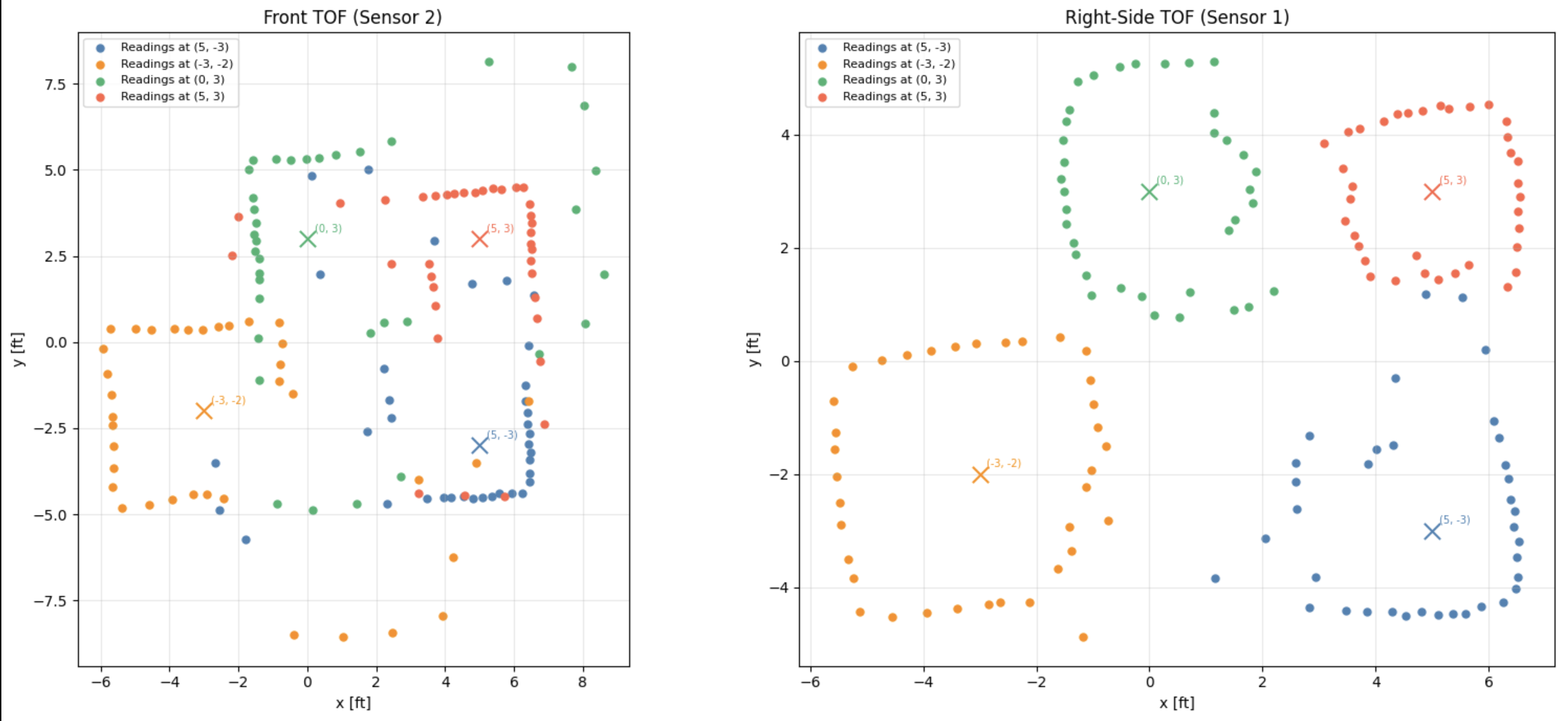
During testing, sensor 1 (right-side mounted) produced readings that formed a tight circular ring around the robot position rather than reaching out to the walls. After investigation, this was found to be caused by the sensor’s physical mounting angle — sensor 1 was pointing slightly downward toward the floor rather than perfectly horizontal. As the robot rotated, the sensor consistently hit the floor at a short, nearly constant distance regardless of heading, producing the characteristic radius-around-robot pattern visible in the scatter plot below. Because of this, the final map is informed by sensor 2 (front-facing).
Angle Corrections
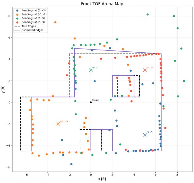
After plotting the combined scatter, I found that two of the four scan positions required a 180° angular correction to align their data with the room’s coordinate frame. Specifically, the scans at (0, 3) and (5, -3) required a 180° correction, while (-3, -2) and (5, 3) required none. Since all four scans were performed within the same BLE session — meaning the DMP never re-initialized and its yaw reference remained consistent throughout — the offset is most likely due to a slight inconsistency in how the robot was placed at those two positions. The correction was applied after processing the data as an angular offset added. The resulting point clusters from all four positions align consistently with the known wall geometry.
Line-Based Map
I manually drew estimated wall segments through the point clusters in the scatter plot. The estimated edges were shifted slightly inward from the true edges in some areas.
Below you can see how the values changed:
# ─────────────────────────────────────────────────────────────────────────────
# TRUE EDGES
# ─────────────────────────────────────────────────────────────────────────────
true_walls_ft = np.array([
    # Outer boundary
    [-6.5, -4.5,  6.5, -4.5],   # bottom
    [ 6.5, -4.5,  6.5,  4.5],   # right
    [ 6.5,  4.5, -2.0,  4.5],   # top right
    [-2.0,  4.5, -2.0,  0.5],   # step down
    [-2.0,  0.5, -6.5,  0.5],   # top left
    [-6.5,  0.5, -6.5, -4.5],   # left

    # Interior box obstacle
    [ 2.5,  0.5,  2.5,  2.5],   # left side of box
    [ 2.5,  2.5,  4.5,  2.5],   # top of box
    [ 4.5,  2.5,  4.5,  0.5],   # right side of box
    [ 4.5,  0.5,  2.5,  0.5],   # bottom of box

    # Bottom center obstacle
    [-1.0, -4.5, -1.0, -2.5],   # left side
    [-1.0, -2.5,  1.0, -2.5],   # top
    [ 1.0, -2.5,  1.0, -4.5],   # right side
])

# ─────────────────────────────────────────────────────────────────────────────
# ESTIMATED EDGES
# ─────────────────────────────────────────────────────────────────────────────
estimated_walls_ft = np.array([
    # Outer boundary
    [-5.5, -4.5,  6.5, -4.5],   # bottom
    [ 6.5, -4.5,  6.5,  4.5],   # right
    [ 6.5,  4.5, -1.5,  5.0],   # top right
    [-1.5,  5.0, -1.5,  0.5],   # step down
    [-1.5,  0.5, -5.5,  0.5],   # top left
    [-5.5,  0.5, -5.5, -4.5],   # left

    # Interior box obstacle
    [ 2.0,  0.5,  2.0,  2.5],
    [ 2.0,  2.5,  4.0,  2.5],
    [ 4.0,  2.5,  4.0,  0.5],
    [ 4.0,  0.5,  2.0,  0.5],

    # Bottom center obstacle
    [ 0.0, -4.5,  0.0, -2.5],
    [ 0.0, -2.5,  2.0, -2.5],
    [ 2.0, -2.5,  2.0, -4.5],
])
starts = [(-1981.2, -1371.6), (1981.2, -1371.6), (1981.2, 1371.6), (-609.6, 1371.6), (-609.6, 152.4), (-1981.2, 152.4), (762.0, 152.4), (762.0, 762.0), (1371.6, 762.0), (1371.6, 152.4), (-304.8, -1371.6), (-304.8, -762.0), (304.8, -762.0)]
ends   = [(1981.2, -1371.6), (1981.2, 1371.6), (-609.6, 1371.6), (-609.6, 152.4), (-1981.2, 152.4), (-1981.2, -1371.6), (762.0, 762.0), (1371.6, 762.0), (1371.6, 152.4), (762.0, 152.4), (-304.8, -762.0), (304.8, -762.0), (304.8, -1371.6)]
Wall Offset Due to Drift
Some of the estimated wall positions are slightly shifted from the true edges — most noticeably the left wall and parts of the top boundary. I belive this is caused by the drift of the car while its turning during the mapping scan. Even though I used orientation PID to control heading, the robot does not spin perfectly on-axis. Each incremental turn causes a small sideways displacement of the robot’s physical center. Over the course of a full 36-step scan, these small displacements accumulate, making the robot’s actual position at the time of each reading slightly different from the marked position it started at. This is a problem because the transformation assumes the robot remains stationary at its starting coordinates throughout the entire scan.
Outliers Beyond Room Boundary
Several scatter points land outside the known room boundary. This is likely caused by sensor 2 being mounted at a slight upward angle. When the sensor points toward a distant wall, the upward tilt means the beam grazes above the wall rather than hitting it, returning either a very long reading or missing the wall entirely and hitting nothing at all. For example, readings from (0,3) pointing toward the top wall.
Discussion
In this lab I learned how to produce a line-based map using orientation-PID-controlled incremental scanning. The main challenges were sensor 1’s downward mounting angle — which caused it to read the floor instead of walls, producing a circular ring pattern in the scatter plot — and translational drift during spins, which shifted some wall clusters.
References
I used Stephan Wagner’s page for guidance on a couple of plots and the manual tracing procedure. I attended office hours and Lucca was extremely helpful helping me realize the sensor facing downward problem. I gave my car to Hayden Webb for a couple hours so he could run his code. Hayden Webb’s car broke down, he could not collect data and so I shared my data with him. Claude helped me make very pretty plots.